

Description
Payment & Security
Your payment information is processed securely. We do not store credit card details nor have access to your credit card information.
Follow Us


Overview
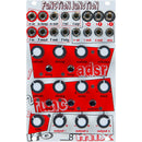
According to the user manual, “Function Junction is a modulation hub combining four independent sections into a single intertwined module that offers much more than the sum of its parts. Although a sum of its parts is one of its best features!” I think what the ultra-serious manual writer was trying to say is that Function Junction can do more than a ton of things. In fact, it’s downright impressive what’s possible with this lovely module.
A party of functions
Function Junction came about because one of our product managers was bothering our serious friends (we like them at least) at Pittsburgh Modular Synthesizers. They were complaining that many-function-in-one modules were confusing to use and were trying to accomplish too much, and therefore not really good any single function. Oddly, the stoic folks at Pittsburgh Modular agreed with him (for once) and took this as a challenge. A few days later they came back with what would be the panel design for this module.
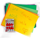
Function Junction combines three classic analog modulation sources, ADSR envelope, function generator, and LFO. All are fed into an attenuverting mixer to create a complex modulation junction that can be used as 4 independent sections or in conjunction with each other.
The magic of the module is the ease you can flow from using its functions for basic everyday tasks to creating hyper-complex modulation. The sheer breadth of what you can do and the ease of doing it are pretty amazing (if we don’t say so ourselves).
Normally we’re not manual readers, but in this case we highly recommend reading the manual to get a feel for the possibilities. Don’t worry, you can go back to playing Space Invaders after you get done reading.
Features
Your payment information is processed securely. We do not store credit card details nor have access to your credit card information.
We have a 30-day return policy, which means you have 30 days after receiving your item to request a return.
To be eligible for a return, your item must be in the same condition that you received it, unworn or unused, with tags, and in its original packaging. You’ll also need the receipt or proof of purchase.
To start a return, you can contact us at sales@sweetheartdeals.com. If your return is accepted, we’ll send you a return shipping label, as well as instructions on how and where to send your package. Items sent back to us without first requesting a return will not be accepted.
You can always contact us for any return question at sales@sweetheartdeals.com.
Damages and issues
Please inspect your order upon reception and contact us immediately if the item is defective, damaged or if you receive the wrong item, so that we can evaluate the issue and make it right.
Exceptions / non-returnable items
Certain types of items cannot be returned, like perishable goods (such as food, flowers, or plants), custom products (such as special orders or personalized items), and personal care goods (such as beauty products). We also do not accept returns for hazardous materials, flammable liquids, or gases. Please get in touch if you have questions or concerns about your specific item.
Unfortunately, we cannot accept returns on sale items or gift cards.
Exchanges
The fastest way to ensure you get what you want is to return the item you have, and once the return is accepted, make a separate purchase for the new item.
Refunds
We will notify you once we’ve received and inspected your return, and let you know if the refund was approved or not. If approved, you’ll be automatically refunded on your original payment method. Please remember it can take some time for your bank or credit card company to process and post the refund too.
Free shipping within the continental United States
Additional charges may apply when shipping to AK, HI and Puerto Rico. Most orders ship within 1-3 business days.
Free 30-day Returns
Not satisfied with your purchase? Return within 30 days for a full refund. We pay the shipping back!
Superior Support
Have a question about your purchase or need technical assistance? Call us at 1-888-507-1180 and we will assist!
Secure Payments
All transactions are certified Level 1 PCI DSS compliant, which means peace of mind at checkout!
